加入好友
Home
1
Information
2
Uncategorized
3
Knowledge Share #11 – Installation and Technical Key Points of a Large 4th-Axis Rotary Table4
https://www.herbao.com.tw/en/ HER BAO MACHINERY CO., LTD.
HER BAO MACHINERY CO., LTD. 1 F., No. 10-59, Yuangang, 2nd Neighborhood, Yuangang Vil., Yuanli Township, Miaoli County 35852, Taiwan (R.O.C.)
  Why Are Robotic Arms So Precise?Understanding Hypoid Gears: Principles, Advantages, and Applications When it comes to high-precision transmission systems, Hypoid Gears are a type of gear commonly used in industry, although many people may not be familiar with them.In recent years, with the rapid development of automation equipment, robotic arms, and smart manufacturing, transmission systems are no longer expected to provide only power. They must also deliver high precision, low noise, and stable operation. Hypoid gears are a transmission solution well suited for these demands.From robotic arms and precision positioning equipment to advanced automation systems, hypoid gears can be found in a wide range of applications. Their biggest advantages are large tooth contact area, smooth operation, high rigidity, while also maintaining good transmission efficiency and low noise performance.So, what exactly is a hypoid gear, and how is it different from ordinary gears? What Is a Hypoid Gear? How Is It Different from Ordinary Gears? A hypoid gear is a special type of bevel gear transmission structure. Its most distinctive feature is that the two transmission shafts do not completely intersect, but instead use an offset design.Compared with ordinary gears, hypoid gears feature three-dimensional curved tooth surfaces, deeper tooth geometry, and a larger contact area. During operation, the transmitted force is not concentrated at a single contact point. Instead, it is distributed more evenly across a larger tooth surface area, which helps reduce vibration and impact.Because of this larger contact area, hypoid gears can maintain smooth and stable operation even under high loads, while also providing lower noise performance. Compared with traditional gears, hypoid gears typically offer the following characteristics:• Larger tooth surface contact area• High operational stability• Lower noise levels• Higher rigidity• Suitable for high-load and high-precision transmission applicationsThis is why hypoid gears are commonly used in precision machinery and advanced automation equipment.  Transmission Principles of Hypoid Gears  The transmission mechanism of hypoid gears falls between helical gears and worm gears.They are not purely rolling contact like helical gears, nor do they rely heavily on sliding friction like worm gears. Instead, hypoid gears use large-area tooth surface engagement to distribute force more evenly during transmission.As hypoid gears operate, the tooth surfaces engage in a continuous and progressive manner. This helps reduce sudden impact and vibration during power transmission, resulting in smoother overall operation.In addition, the offset design of hypoid gears provides greater flexibility in structural layout, allowing them to achieve both high torque and high rigidity within limited installation space.In simple terms, hypoid gears offer several key transmission characteristics:• High transmission stability• Excellent load-carrying capability• Lower noise levels• Stable torque output• Outstanding rigidity and precisionBecause of these advantages, hypoid gears are especially suitable for equipment that requires long-term, high-precision operation.  Manufacturing Process of Hypoid Gears  Compared with ordinary gears, hypoid gears are more difficult to manufacture.Because hypoid gears feature three-dimensional curved tooth surfaces, the machining process involves much more than simply cutting gear teeth. Every angle and tooth surface contact geometry must be precisely controlled to ensure proper meshing accuracy. Typical manufacturing processes for hypoid gears include:• Rough machining• Five-axis machining• Heat treatment• Tooth surface grinding• Precision finishing and correction machining Among these processes, five-axis machining is one of the most critical steps in hypoid gear manufacturing. Due to the complex tooth surface geometry of hypoid gears, multi-axis synchronized machining is required to produce the correct curved tooth profile.After machining is completed, multiple grinding and correction processes are usually performed to improve tooth contact accuracy and reduce operational error and noise.Because of the high manufacturing complexity, hypoid gears require extremely high standards in machine precision, machining technology, and measurement capability.  How Are Hypoid Gears Measured and Inspected?  Because hypoid gears feature more complex tooth surface structures, their measurement and inspection processes are even more important than those of ordinary gears. Common inspection items for hypoid gears include:• Tooth profile measurement• Tooth contact pattern inspection• Transmission error testing• Gear meshing accuracy inspection Among these inspections, tooth contact pattern analysis is one of the most important for hypoid gears. Since hypoid gears transmit force through large-area tooth surface contact, the uniformity and stability of the contact pattern directly affect operational performance.Transmission error is also a critical indicator. By measuring variations during rotation, it is possible to verify whether the gear can maintain stable and smooth operation under high-speed or high-load conditions.Especially in precision equipment, even very small errors can affect positioning accuracy and overall system performance.  Advantages of Hypoid Gears  The greatest advantage of hypoid gears is their ability to combine high rigidity, high precision, and low noise performance at the same time.Because they have a larger tooth surface contact area, loads can be distributed more evenly during power transmission, reducing localized stress and vibration. Even under high-load operating conditions, hypoid gears can still maintain stable and smooth performance. Compared with other transmission systems, hypoid gears offer several significant advantages:1. High RigidityThe offset design combined with large-area tooth surface contact improves overall structural rigidity, making hypoid gears suitable for high-load applications.2. High PrecisionStable tooth surface engagement helps maintain excellent positioning accuracy and transmission stability.3. Low NoiseThe smoother tooth meshing process effectively reduces vibration and operating noise.4. Stable Torque OutputEven under increased loads, hypoid gears can still maintain smooth and stable power transmission.5. Suitable for Precision EquipmentThey are especially suitable for equipment requiring high-precision control and long-term operation.  Common Applications of Hypoid Gears  In recent years, hypoid gears have become increasingly common in automation equipment and robotic arms.During operation, robotic arms must simultaneously maintain load capacity, positioning accuracy, and smooth motion. As a result, the transmission system requires high rigidity and stable torque output—both of which are key advantages of hypoid gears.Compared with ordinary gears, hypoid gears provide a larger tooth surface contact area, allowing them to maintain smooth operation, low vibration, and low noise even under high-load conditions. This makes them especially suitable for precision control equipment. In addition to robotic arms, hypoid gears are also widely used in:• Precision positioning platforms• CNC machine tools• Automation equipment• Semiconductor equipment• High-precision rotary tables• Industrial robots Especially in equipment that requires long-term, high-precision operation, hypoid gears can effectively improve overall stability and transmission performance.  Conclusion: Why Are Hypoid Gears Becoming More Important?  With the rapid development of automation and smart manufacturing, transmission systems are no longer expected to simply "move." Today, the industry places greater emphasis on:• High precision• High rigidity• Low noise• Operational stability• Long-term operating capability ( Related Reading How to Install Large Worm Gear Rotary Tables? | Knowledge Sharing EP.11 – Installation and Technical Considerations for Large Rotary Tables ) Herbao Machinery will continue driving technological innovation and providing customers with more professional and reliable solutions.If you have any technical questions, feel free to contact us! https://www.herbao.com.tw/en/hot_533876.html Knowledge Share #12 – Why Are Robotic Arms So Precise? Understanding Hypoid Gears: Principles, Advantages, and Applications 2026-05-21 2027-05-21
HER BAO MACHINERY CO., LTD. 1 F., No. 10-59, Yuangang, 2nd Neighborhood, Yuangang Vil., Yuanli Township, Miaoli County 35852, Taiwan (R.O.C.) https://www.herbao.com.tw/en/hot_533876.html
https://schema.org/EventMovedOnline https://schema.org/OfflineEventAttendanceMode
2026-05-21 http://schema.org/InStock TWD 0 https://www.herbao.com.tw/en/hot_533876.html
TIMTOS 2027!Coming Soon!敬請期待!


Installation and Technical Key Points of
A Large 4th-Axis Rotary Table


In CNC machining, a 4th-axis rotary table is an essential component that enables efficient multi-face machining of complex parts. It not only enhances angular flexibility but also determines machining speed, precision, and overall stability. In this article, we present a real-world case study showing how we replaced and integrated a heavy-duty 4th-axis unit on a CNC machining center with a 1.4-meter travel. We dive into the technical reasoning and precision requirements behind each step, guiding you through the complete installation process and helping you understand the key principles of 4th-axis integration.

 Why Replacing the 4th Axis Is Necessary: The Impact of Precision Degradation 

The customer’s original 4th-axis rotary table had been in service for many years and had developed significant issues, including severe loss of repeatability, increased positioning errors, and brake system failure.
Once the precision of a 4th axis deteriorates, it directly leads to several machining problems:

• Amplified angular errors during multi-face machining
• Reduced surface quality of machined parts
• Increased vibration or wobble during long-part rotation
• Machine compensation unable to resolve the root cause of inaccuracy


 Electrical Integration Test: Ensuring Compatibility Between the CNC and 4th Axis 

Before installing the new 4th axis onto the machine, it is essential to verify that the CNC controller can properly drive it.
All control cables must be connected, followed by electrical tests including rotation direction, speed response, brake engagement, and servo feedback.
Performing these checks in advance prevents issues such as mismatched parameters, unrecognized signals, or brake malfunction after installation.

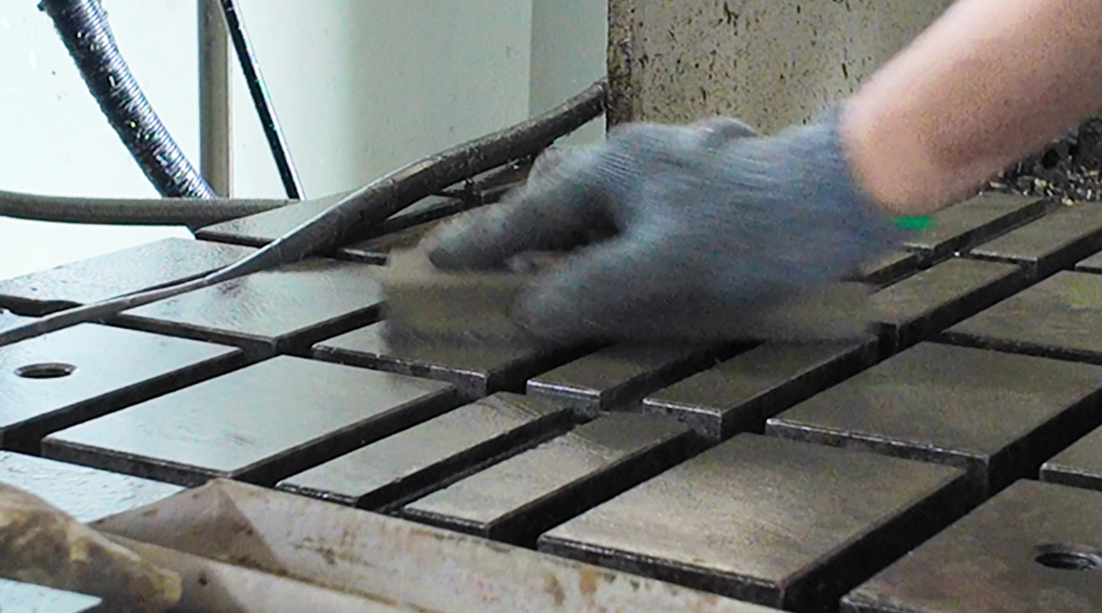
Worktable Flatness Preparation:
The Foundation of High-Precision Installation 

The machine's worktable serves as the fundamental reference surface for all subsequent machining.
To ensure accuracy, we carefully scrape the table surface with an oil stone to remove burrs, tool marks, tiny high spots, and machining debris.
A clean and perfectly flat surface is the first and most critical step in maintaining the geometric accuracy of the newly installed 4th axis.
Installing the Positioning Key:
Ensuring the 4th Axis Returns to the Exact Reference 

After applying anti-rust oil to the base of the new 4th axis, a positioning key is installed.
This small but essential component establishes a fixed reference between the rotary table and the machine table.
It prevents positional shifts caused by long-term machining vibrations and allows the 4th axis to return to its original precise location even after future removal or maintenance.

 Tailstock and 4th-Axis Positioning: Establishing a Complete Rotational Support System 

The 4th-axis body and the tailstock must be placed on the machine table simultaneously. Initial measurements are taken to estimate the fixture plate location and the alignment of all contact surfaces. After cleaning the tailstock, we again use an oil stone to refine its mounting surface. This ensures that the center height of the 4th axis and tailstock are perfectly matched, providing balanced support for long workpieces during rotation and preventing vibration or runout caused by eccentric loading.

 4th-Axis Parameter and Operation Testing 

Before final tightening, we test all operating conditions of the 4th axis, including:
• Rotational speed
• Direction accuracy
• Brake positioning precision
• Smoothness of movement and absence of abnormal noise

These checks verify that the system is functioning correctly prior to final installation.

 Parallelism Calibration: Maintaining Geometric Consistency with the CNC Machine 

The rotational axis of the 4th axis must be perfectly parallel to the CNC machine’s Y-axis. Using a dial indicator, we perform multi-point measurements and repeatedly adjust until the deviation falls within the required tolerance. After tightening the mounting bolts, the calibration is performed once more to ensure no positional shift occurred during fastening.

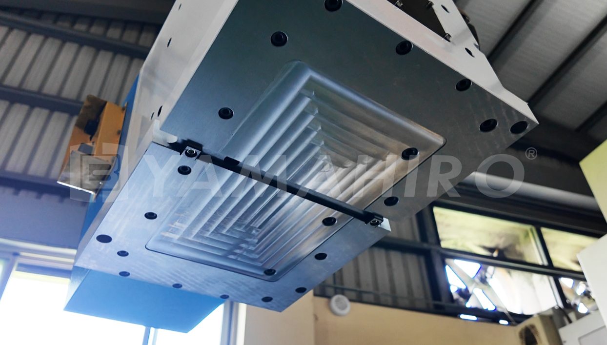
 Fixture Plate Installation 

Before installing the fixture plate, both the machine table and fixture plate mounting surfaces must be rechecked with an oil stone to ensure flatness. Once the fixture plate is pre-mounted, we adjust four critical geometric parameters—concentricity, center height, parallelism, and perpendicularity. These precision alignments determine whether the 4th axis can reliably support workpieces and maintain accurate positioning during future machining operations.


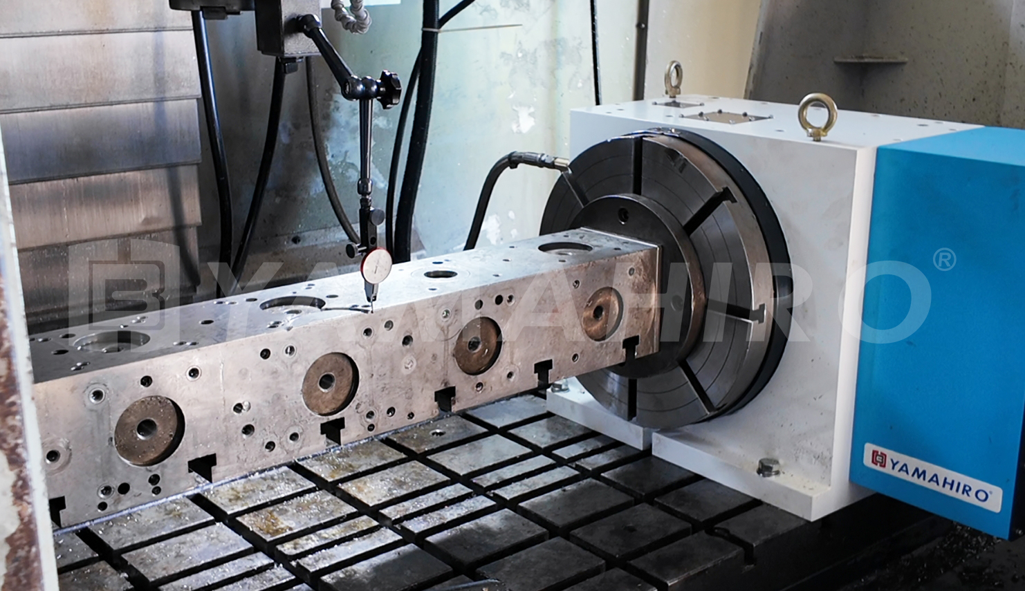
 Test Run and Actual Machining: The Final Verification of the Entire System 

After completing all precision adjustments, a full test run is conducted to verify system performance.
We ensure that the entire rotary table assembly operates smoothly, without abnormal noise, vibration, or irregular motion.
Once these conditions are confirmed, the integration of the large heavy-duty 4th axis is officially complete, and the machine is ready for real machining applications.

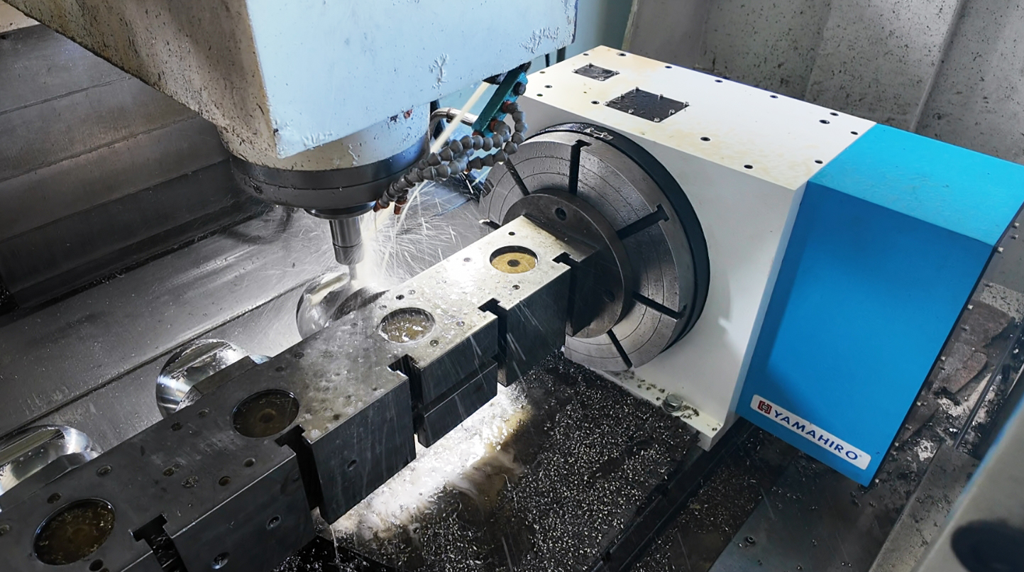
 Conclusion: Installing a 4th Axis Is a Complete Precision Engineering Process 

The installation of a 4th-axis rotary table is not simply a mechanical replacement—it is a comprehensive precision engineering task.
It involves evaluating worktable conditions, ensuring electrical compatibility, synchronizing hydraulic systems, performing geometric calibration across multiple axes, and adjusting fixture plate flatness and parallelism.

Every step must be executed correctly and every measurement verified to ensure that the CNC machining center can fully leverage the capabilities of the 4th axis.
When done properly, the machine achieves high precision, high efficiency, and exceptional stability across multi-angle and multi-face machining tasks.

If you are considering upgrading to a 4th axis, integrating a heavy-duty rotary table, or facing challenges in precision calibration, Herbao Machinery is ready to provide professional assistance and help you enhance your production capabilities.


 Common Questions About Large 4th-Axis Installation (FAQ) 

Q1:When should a 4th-axis rotary table be replaced?
A:A 4th axis will naturally wear over long-term use, leading to reduced repeatability, increased positioning errors, weakened brake performance, or abnormal noise.
If these issues begin to affect machining accuracy or can no longer be corrected through adjustment, replacement becomes necessary.

Q2:Why is it necessary to remove burrs and high spots on the worktable with an oil stone?
A:Any remaining metal chips or tiny high spots on the worktable can cause misalignment during installation.
This may lead to angular errors or parallelism issues during 4th-axis rotation.
Oil stone scraping ensures a smooth, accurate reference surface for installation.

Q3:What is a positioning key?
A:A positioning key is a reference slot or key used to lock the 4th axis into a precise mounting position.
It ensures that the rotary table returns to the exact same location after removal or maintenance, preventing positional drift caused by vibration or thermal deformation.
This greatly reduces recalibration time and improves machining consistency.

Q4:What happens if the center height of the 4th axis and tailstock does not match?
A:If their center heights are inconsistent, the workpiece will experience uneven forces during rotation, resulting in vibration, chatter, irregular tool marks, or even deformation.Therefore, precise measurement and alignment of center height are essential.

Q5:Is a test run required after installation?
A:Yes.
A test run checks for abnormal noise, binding, vibration, or delayed hydraulic response.
It ensures the entire system is functioning correctly before real machining begins.

Q6:What machining benefits does a 4th axis provide?
A:Installing a 4th axis significantly enhances:
• Multi-angle machining flexibility
• Capability for spherical, angled, and curved-surface machining
• Machining speed and efficiency in multi-face operations
• Workpiece consistency
• Overall production throughput


Herbao Machinery continues to drive technology innovation, providing professional and reliable machining solutions.
If you have any technical questions or application challenges, feel free to contact us anytime!

Previous Back to List Next